

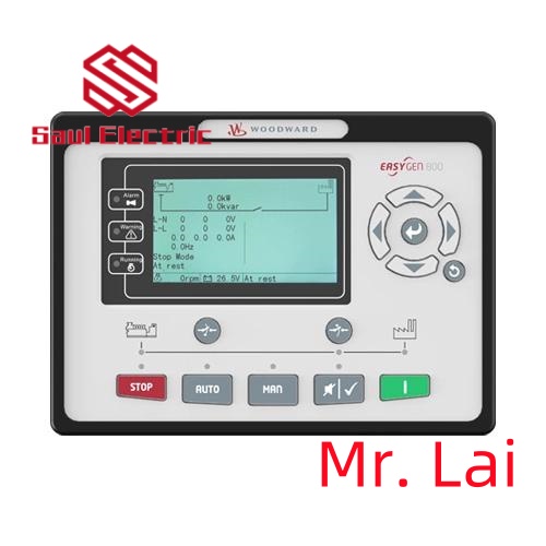
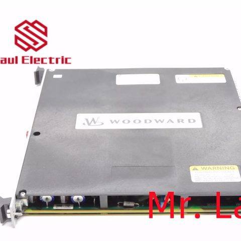
Woodward 5439-861 |CPU Module, Origin: United States
1.5439-861 Product Overview

The Woodward 5439-861 belongs to the 505/505E series digital turbine controllers. It is a microprocessor-based control module designed for single-valve steam turbines,
including single extraction/admission systems or split-range actuator configurations.
The controller features a front panel Operator Control Panel (OCP) with a two-line, 24-character display and multi-function keypad, allowing easy on-site configuration and monitoring.
contacts: Mike
+86 18350224834 (WeChat/WhatsApp)
Email:Mike18350224834@gmail.com
2. 5439-861 Technical Specifications and Parameters
| Parameter | Details |
|---|---|
| Power Supply | +24 VDC, approx. 1 A |
| I/O Outputs | Discrete Outputs: 8 Analog Outputs: 6 Actuator Outputs: 2 |
| Display / HMI | Two-line, 24-character LCD, with multi-function keypad |
| Dimensions | Approx. 14 × 11 × 4 in (35.6 × 27.9 × 10.2 cm) |
| Weight | Approx. 9.11 lbs (4.13 kg) |
| Operating Temperature | –4 to +140 °F (–20 to +60 °C) |
| Storage Temperature | –40 to +185 °F (–40 to +85 °C) |
| Humidity Standard | 95% RH at 20-55 °C for 48 hours without damage |
| Protection Class | Typically meets industrial dust and water protection standards |
| Communication Protocol | Supports Modbus, RS-232 / RS-422 serial interfaces |

3. Brand History
Woodward, Inc., founded in 1870 and headquartered in Fort Collins, Colorado, USA, is a global leader in energy control systems. The company has a long history of innovation in turbine control, engine management,
and power generation systems.
Woodward products are widely recognized for their reliability and precision in demanding industrial and power generation applications.
4. Applications in Industrial Automation
The 5439-861 plays a critical role in industrial automation and power generation environments:
- Steam Turbine Control: Manages startup, speed regulation, and extraction/admission control of steam turbines.
- Power Generation Systems: Used in power plants to regulate turbine-driven generators for stable frequency and load management.
- Compressor and Pump Drive Control: Ensures precise speed control for turbine-driven compressors and pumps.
- Process Industry Applications: Applied in chemical plants, refineries, and other industries requiring precise turbine operation.
- Safety and Protection Functions: Includes overspeed protection, critical speed avoidance, actuator travel limits, and event logging for operational safety.

Explanation: 1. SRV-CTRL refers to the servo control module of PLC;
2. Take the → pointer as input and the ← pointer as output.
3. The meanings of each signal are as follows:
INH: Prohibit input of pulse commands (prohibited when open circuit);
OZ -: Z-phase output;
OZ+: Z-phase output;
S-RDY: The servo drive is ready;
ALM: Servo drive fault alarm;
COIN: Positioning completed;
SRV-ON: servo drive “on” signal;
COM -: Negative pole of power supply;
COM+: Positive pole of power supply;
PULS1: Command pulse input terminal;
PULS2: Command pulse input terminal;
SIGN1: Command pulse symbol input terminal;
SIGN2: Command pulse symbol input terminal;
Servo Drive Wiring Guide
In the field of industrial control automation, many devices have strict installation specifications. So, in order to avoid usage
risks and eliminate safety hazards, what are the rules for connecting servo drives?
1. It is recommended to use a three-phase isolation transformer for power supply to reduce the possibility of electric shock.
2. It is recommended to use a noise filter for power supply to improve anti-interference ability.
3. Please install a non melting short-circuit circuit breaker to promptly cut off external power in case of driver failure.
4. The grounding wire should be ≥ 2.5m2, as thick as possible, and made into a single point grounding.
The grounding terminal of the servo motor must be connected to the grounding terminal PE of the driver.
5. Connect the shielding layer of the cable correctly.
To prevent interference and misoperation, it is recommended to install a noise filter and pay attention to:
(1) The noise filter, servo drive, and upper controller should be installed as close as possible.
(2) Surge suppressors must be installed in relays, AC contactors, brakes, and other coils.
(3) Power circuit cables and signal lines should not be tied together.
Click to learn more about Woodward”s products
Philips 7122 714 1400.4 Processor PCB Card MCDM 60 1,6 ASML PAS 50002500
SVG 99-46450-01 9200SE SVG ASML 90 track Z-robot, 23074-01-D, 110164
ASML 4022.639.86642 IR1-NIR Solid State Laser Module ELEC-I-1739=9C
VERSALOGIC VL-7709BY ASML 854-2343-002 PCB
SVG Silicon Valley Group 851-9075-010 Wafer Handling Robot ASML Working Surplus
ASML 4022.639.86653 Class 3B ( AIGaAs ) 850um 10mW Solid state Laser Module
ASML CO2 NXT SAFETY 4022.642.99854
Agilent 4022.471.78842 WIPA PPCA VMEbus PCB Card ASML New Surplus
ASM INTERNATIONAL N.V. 2374110-01 INJECT GAS DIV RING LPC FR M
ASML Laser Mat: 4022.472.42562 532nm Class 3B ( NdYVO4) ) Laser Module
ASML 4022.640.59951
1PS HIB293 ID 630820-03 L12 ASML 4022.640.59951 (3-month warrantySHIP FedEx)
14066 ASML MODULE BOARD SVG MOTION CONTROLLER, PCB 4022.471.6982
28319 ASML PCB ASSY, SINGLE BD COM, MVME 167-32B, 01-W3899B32C 4022.436.8131
Philips PC 172110 Processor PCB Card ASML 9406.217.2110 PAS 50002500
ASML 4022.472.42602 Class 3B ( AIGaAs ) 780nm 10mW Solid state Laser Module
ASML Intermolecular 500084 Interconnect M&D PCB Rev.D Serial# 040408ALTA005
ASML 402250245116 ENCL 1000W TCU REPL BY 2500W
ASML 4022.430.2048 Mains Switch Unit 4022.428.1761.
ASML 854-9501-002 RETICLE, MICRASCAN III, 4X
SVG Lithography Systems 854-0056-822 ASML
ASML 4022.639.86644 IR1-NIR ELEC-I-1001=8F


There are no reviews yet.