

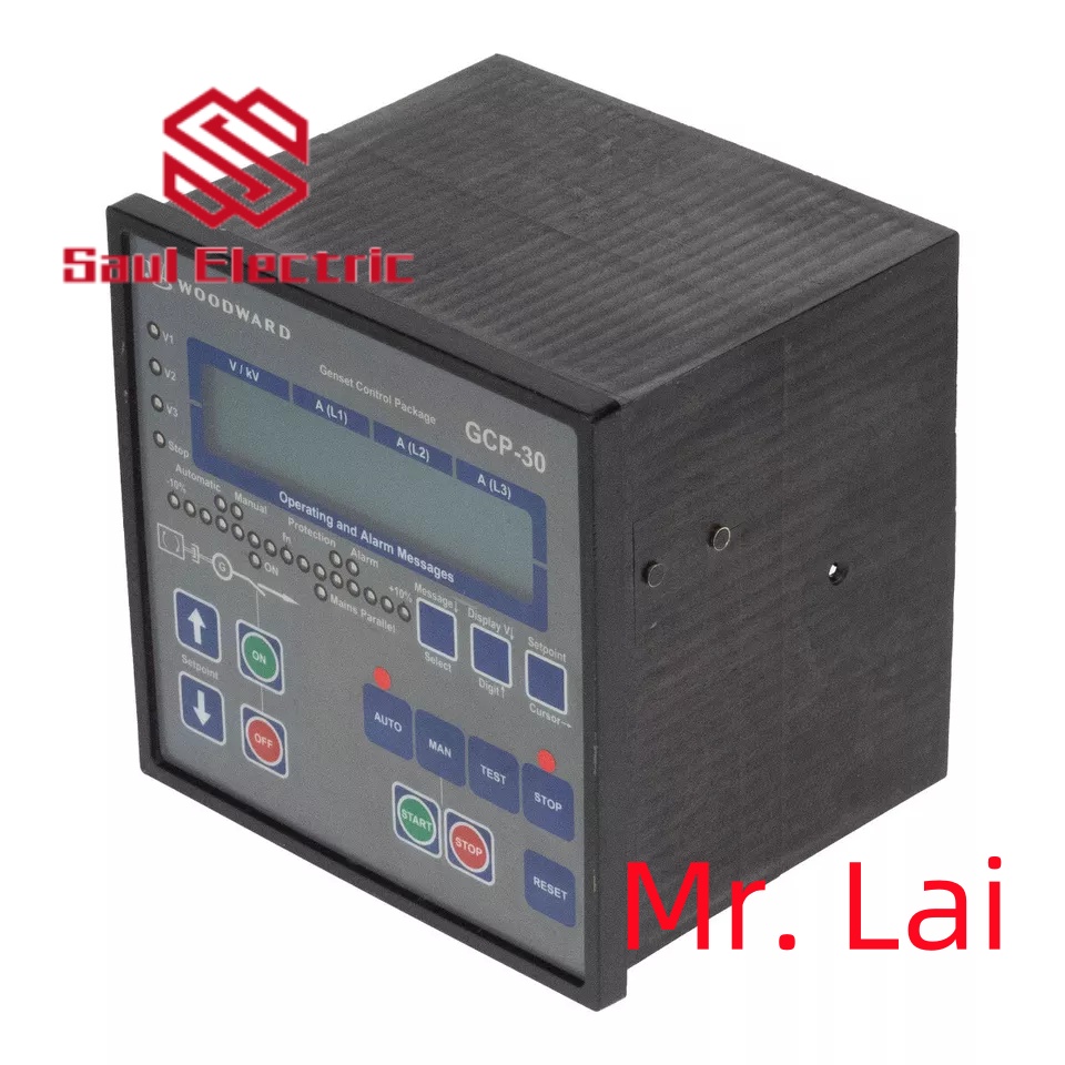
Woodward 8272-464 |CPU Module, Origin: United States
1.8272-464 Product Overview

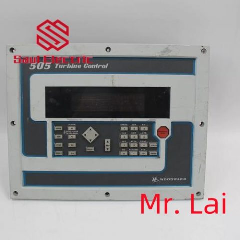
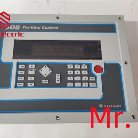
The Woodward 8272-464 belongs to the 505/505E series digital turbine controllers. It is a microprocessor-based control module designed for single-valve steam turbines,
including single extraction/admission systems or split-range actuator configurations.
The controller features a front panel Operator Control Panel (OCP) with a two-line, 24-character display and multi-function keypad, allowing easy on-site configuration and monitoring.
contacts: Mike
+86 18350224834 (WeChat/WhatsApp)
Email:Mike18350224834@gmail.com
2. 8272-464 Technical Specifications and Parameters
| Parameter | Details |
|---|---|
| Power Supply | +24 VDC, approx. 1 A |
| I/O Outputs | Discrete Outputs: 8 Analog Outputs: 6 Actuator Outputs: 2 |
| Display / HMI | Two-line, 24-character LCD, with multi-function keypad |
| Dimensions | Approx. 14 × 11 × 4 in (35.6 × 27.9 × 10.2 cm) |
| Weight | Approx. 9.11 lbs (4.13 kg) |
| Operating Temperature | –4 to +140 °F (–20 to +60 °C) |
| Storage Temperature | –40 to +185 °F (–40 to +85 °C) |
| Humidity Standard | 95% RH at 20-55 °C for 48 hours without damage |
| Protection Class | Typically meets industrial dust and water protection standards |
| Communication Protocol | Supports Modbus, RS-232 / RS-422 serial interfaces |

3. Brand History
Woodward, Inc., founded in 1870 and headquartered in Fort Collins, Colorado, USA, is a global leader in energy control systems. The company has a long history of innovation in turbine control, engine management,
and power generation systems.
Woodward products are widely recognized for their reliability and precision in demanding industrial and power generation applications.
4. Applications in Industrial Automation
The 8272-464 plays a critical role in industrial automation and power generation environments:
- Steam Turbine Control: Manages startup, speed regulation, and extraction/admission control of steam turbines.
- Power Generation Systems: Used in power plants to regulate turbine-driven generators for stable frequency and load management.
- Compressor and Pump Drive Control: Ensures precise speed control for turbine-driven compressors and pumps.
- Process Industry Applications: Applied in chemical plants, refineries, and other industries requiring precise turbine operation.
- Safety and Protection Functions: Includes overspeed protection, critical speed avoidance, actuator travel limits, and event logging for operational safety.

How to wire a BLDC driver? The difference between a BLDC driver and a servo motor driver
How to wire the BLDC driver
The wiring method of BLDC (brushless DC motor) drivers may vary depending on the specific driver model and usage scenario,
but generally speaking, the wiring of BLDC drivers includes the following key parts:
1. Power wiring: BLDC drivers require external power supply. Usually, power wiring includes connecting the positive and negative poles of
a DC power source (such as a battery) to the power input terminal of the driver.
2. Motor wiring: The BLDC driver names the three phase lines on the drive motor shaft as phase A, phase B, and phase C. Motor wiring
generally includes connecting the A-phase, B-phase, and C-phase wires of the driver to the corresponding phase wires of the motor.
3. Sensor wiring (if any): Some BLDC drivers require the connection of sensors such as Hall sensors or encoders to obtain
information on the motor”s rotational position and speed. Sensor wiring generally includes connecting the output signal line
(usually three wires) of the sensor to the corresponding input terminal of the driver.
4. Control signal wiring: BLDC drivers typically require receiving control signals to control parameters such as motor speed
and direction. The control signal wiring usually includes connecting the speed control, direction control, and enable pins of the
driver to the corresponding output pins of the controller (such as microcontroller or PLC).
It should be noted that the wiring method of BLDC drivers is related to the specific driver model, and should refer to the
selected driver”s manual or technical manual for correct wiring. In addition, it is recommended to ensure that the polarity
and wiring of the power and signal lines are correct before wiring, and to follow the rated current and voltage requirements
of the motor and driver to ensure safe and normal operation.
Click to learn more about Woodward”s products
1PCS STATION 662 ASML 4022 197 52062 69741 90days warranty via DHL or FedEx
ASML Laser Mat: 4022.427.42562 Class 3B ( NdYVO4) ) 532nm Laser Module
ASML 2395134-01 SUSPENSION LINER RING LP
wafer chuck ASML SVG Silicon Valley Group wafer grindingcoati
HEINZINGER TNQ”S 500 POWER SUPPLY ASML PAS 25005000 4022.430.07522
ASML Green Laser 4022.455.09864 4022.455.09864
FESTO ASML PNEUMATIC BLOCK FOR 25005000 INC. FUNCTIONS 8,9,10,17,18,1
ASML 4022.430.0759 Processor PCB Card MCDM 60 5,5 PAS 50002500 Working
Philips 7122 714 1800 Power Distribution PCB Card ASML 4022.430.0336 PAS
ASML 859-9623-001 RETICLE SCATTERED LIGHT, QML, M
LASER COUNTER PARTICLE
ASML 854-9501-001 RETICLE FOCUS FLAT
ASML 4022.436.1723 Laser Cam 4022.456.48071 Semiconductor Manufacturing
PHILIPS ASML PROCESSOR PCB BOARD PAS 50002500 PC 172110 9406.217.2110
FEI COMPANY ASML PN 4022 293 1915 Ion Column Power Supply ASML FGSU
ASML 4022.470.6295 RH Handling Box SHB-RH Nikon NES1 Mini Stepper Working
NEW ASML 4022.640.59951
1PCS NEW ASML 4022 197 99123 4022 197 53591 via DHL or FedEx
ASML MCWC Controller 4022.481.28213
ASML 8658017006 PCB ASSEMBLY BOARD
Philips PG 2024 CPU PCB Card ASML PAS 50002500 Wafer Stepper System
SVG Silicon Valley Group 90S ASML Wafer Transport Robot Arm Shuttle Long Cards


There are no reviews yet.